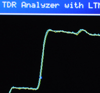
Simple TDR Demonstration
with Altera Cyclone IV GX (ACM-024) Hispeed transceiver and A/D Converter (LTC2274)
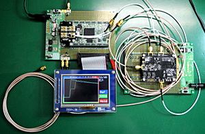
This is a simple demonstration of TDR (Time Domain Refrection) with ACM-024 (Cyclone IV GX) and LTC2274 (Liner Technology's A/D Converter evaluation board).TDR is a one of measurement technique. It uses refrection of pulse signal to measure impedance. This measurement is used to calculate cable length or kind of load.
Components
| Cyclone IV GX FPGA Board | ACM-024 | HuMANDATA |
| SIF40 to MMCX Conversion Board | ACC-010 | HuMANDATA |
| A/D Converter | LTC2274 Evaluation board | Liner Technology |
| 4.3 inch LCD Touch Panel | TRDB-LTM (Discontinued) |
Terasic |
| Download cable | Terasic Blaster | Terasic |
System Architecture and Specifications
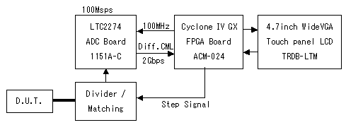
"Divider/Matching" is impedance matching circuit and branches the step signal. |
Sampling Rate | 100Msps |
| Resolution of Phase Shift | 64 steps | |
| Equivalent Sampling Rate | 6.4Gsps | |
| Frequency of Measurement Signal | 167kHz | |
| Time Resolution | 156ps | |
| Cable Length Resolution | 15.9mm | |
| Measurement Time | About 3msec | |
| LCD Reflesh Time | About 35msec |
Need more Resolution
The sampling rate of LTC2274 is 105Msps as maximum, so 100Msps is used to make project simple. This means that time resolution will be 10ns and cable length resolution will be 1 meter. It is not good because a little bit of value differences causes very long length differences. This resolution does not make sence.
Equivalent-Time Sampling
Phase shifting is used to capture the signal in much higher sampling rate. Phase is shifted in 64 steps. The clock used as LTC2274's sampling (encode) clock and used to drive measurement signal are shifted. Measurement point is sampled 64 times then the data are combined in FPGA. Equivalentry, 6.4G points are sampled, so the resolution of cable length is increased to 1.6cm from 1 meter.
In this demonstration, the clock used as LTC2274 sampling clock is not shifted, because it affects the PLL of LTC2274, Cyclone IV high-speed transceiver's CDR(ClockDataRecovery) and phase compensation FIFO of receive data. Insted, the clock drives a logic block in the FPGA generates measurement pulse signal. This way does not affect to the clock phase which used in data conversion logic.
Measurement Circuit
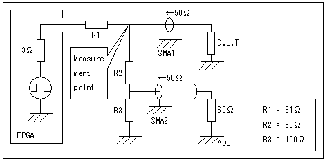 |
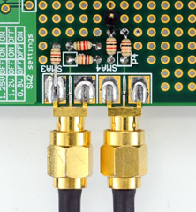
SMA3: A/D SMA4: DUT |
The measurement pulse signal is sampled at the "Measurement point" in above figure. R1 is added to adjust impedance. R2 and R3 is added to divide measurement signal's voltage to meet AD converter's input range. FPGA's input impedance (13 Ohm) and A/D converter's input impedance (60 Ohm) is measured by voltage drop.
FPGA internal architecture

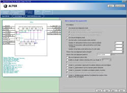
The ALTGX receives serial data and bytealigner aligns the data in correct order. The data divided into 64 parts stored into the "wave_memory" and Nios processor draw waveform on the LCD.

LED display is drew by Nios. LCD pixel data is should be sent at high rate and continiously. A LCD controler sends data from DDR2 memory to LCD in DMA transfer. Rectangular fill is also be processed by hardware to improve display reflesh speed.
Measurement and Waveform
Open (No load)
No load causes no impedance change, so waveform reach to the top with no impedance step.
1.5m coaxial cable
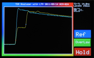
Blue: The stored waveform when measurement point is opened.
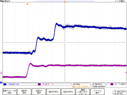
There is 14.8ns time difference between first rising point (Red dot: T1) and second rising point (Blue dot: T2). 14.8ns can be converted into 152cm cable length. It means that TDR can be ised to know cable length. Right figure is same waveform measured by oscilloscope.
1.5m coaxial cable + 50 Ohm terminator
The high level of yellow waveform is at the half of blue waveform by 50 Ohm terminator.
1.5 meter coaxial cable + 2cm SMA connector
Blue: The stored waveform when a 1.5 meter coaxial cable is connected.
2cm SMA connector is attached. 2cm is as same as minimum cable length resolution. Waveform is drew with one pixcel for one data. Yellow waveform made one pixcel difference from blue waveform. It means that minimum resolution is sensed by TDR.
6 meter coaxial cable
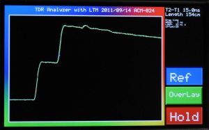
Blue: The stored waveform when measurement point is opened.
More longer half-voltage keeps stable for 61.0 ns (T2-T1). It is more than when 1.5m coaxial cable is connected. 628cm cable length is calculated from 61.0ns
ALTGX Configuration
- Rate:2Gbps
- Reference clock : 125MHz (Onboard)
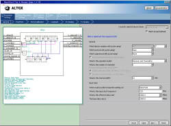
- Rate Match FIFO: Enable
- Skip Pattern: K28.5
- Control Pattern: K28.5
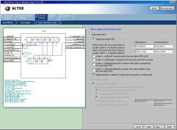
Design files
Please Kindly be forewarned that we do not offer sample design files.
[]


