

ACM-024 Demonstration.
Display a video signal on DSO Nano V2 using Altera Hi-speed Transceiver (ALTGX).
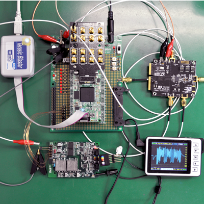
This is an A/D and D/A demonstration using an ACM-024, Altera Cyclone IV GX FPGA board, and an Analog Devices (Linear Technology) LTC2274 evaluation board.
The ACM-024 imports an analog VGA signal (100Msps) and sends data to a D/A converter in slow speed. The DACed analog signal is displayed on Seed Studio, DSO Nano V2. This demonstration is just an example for reference.
Same demonstration using XILINX Spartan-6 is here.
System Configuration
| Components | ||
|---|---|---|
| Cyclone IV GX FPGA Board | ACM-024 | HuMANDATA |
| SIF40 to SMA Conversion Boad | ACC-009 | HuMANDATA |
| A/D Converter | LTC2274 Evaluation board | Analog Devices (Linear Technology) |
| Pocket size Oscilloscope | DSO Nano V2 | Seed Studio |
| Download cable | Terasic Blaster | Terasic |
| Video pattern generator | GV-241 | PROMAX |

The Pattern generator (GV-241) outputs high frequency signals for DSO Nano. In order to monitor signals with DSO Nano, the FPGA slows the rate of data down in 1/100 of original and outputs to UTL-012, isolated 16-bit D/A conversion board, to convert digital data to analog data.
Waveform
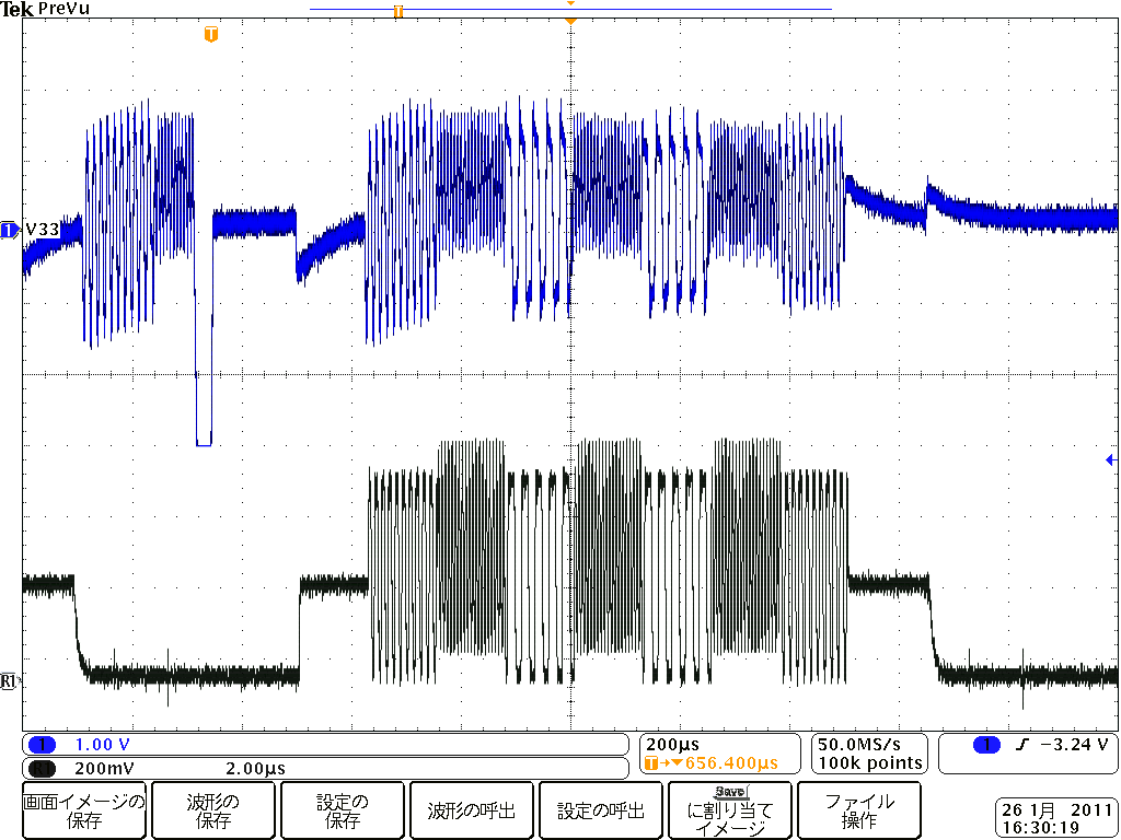
Top is slow-downed waveform by FPGA. A down pulse is added manually for capture.
DC component of a signal is not replayed in DACed waveform because of a limitation comes from A/D converter’s input circuit (About 100kHz or below will be cut off). High-frequency component of signal is reduced its amplitude because of a limitation comes from D/A converter’s slew rate.
Captured A/D data in ACM-024. (using SignalTap)
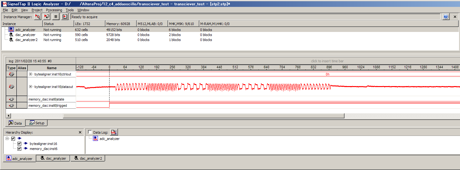
Test video signals make a monochrome striped pattern on a monitor. Sparse and dense pattern matches with above waveform.

Captured waveform (DSO NANO V2)


As you can see, video signal was captured by an affordable oscilloscope.
This demonstration is just only for a demonstration and has no practicality. But we are grad if this gives you some hints for using our products.
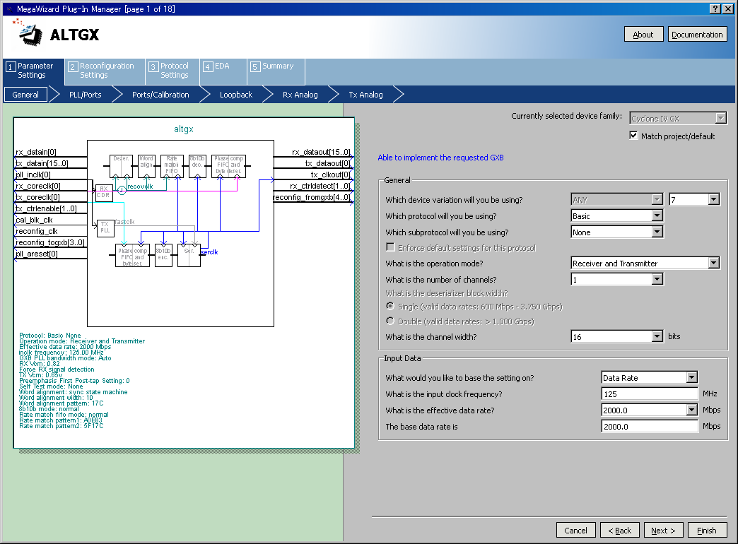
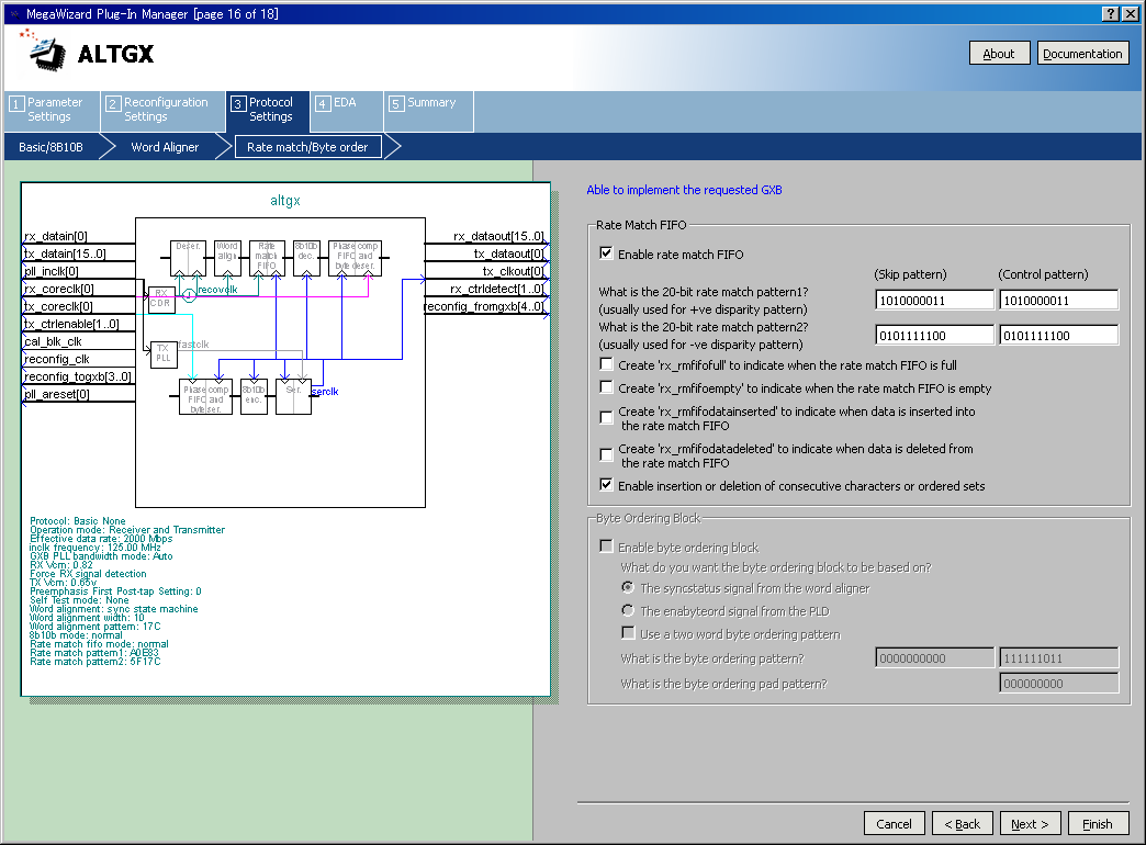
ALTGX Transceiver Setting
- Reference Clock : 125MHz (On-board)

About LTC2274
About DSO Nano V2

Design Files
We hope you find this demonstration informative.
[]